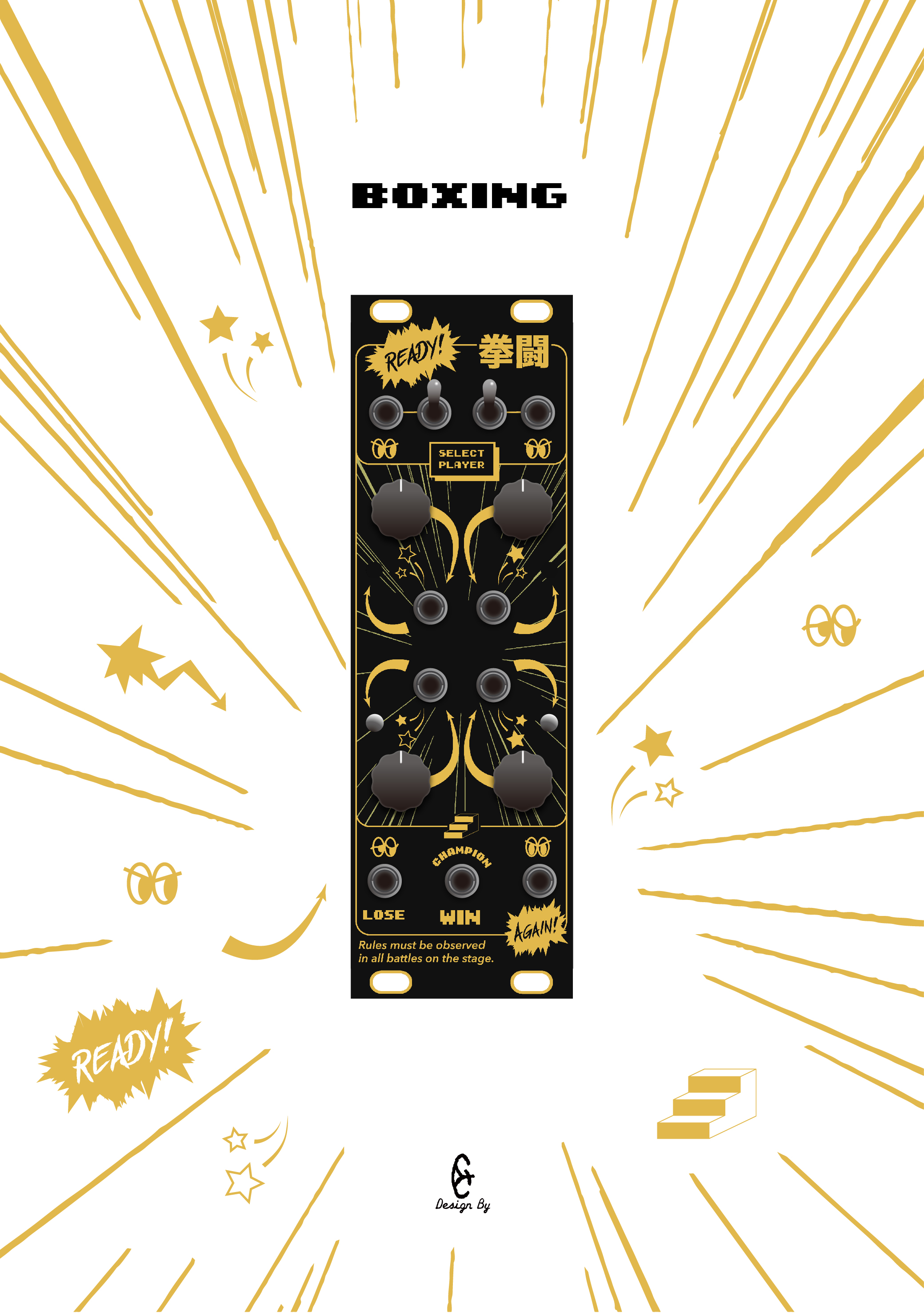
拳斗Boxing是一个以通道选择为基础的多功能模块。它可以实现通道选择、四步进或两步进音序、差分信号、方波、逻辑等功能。
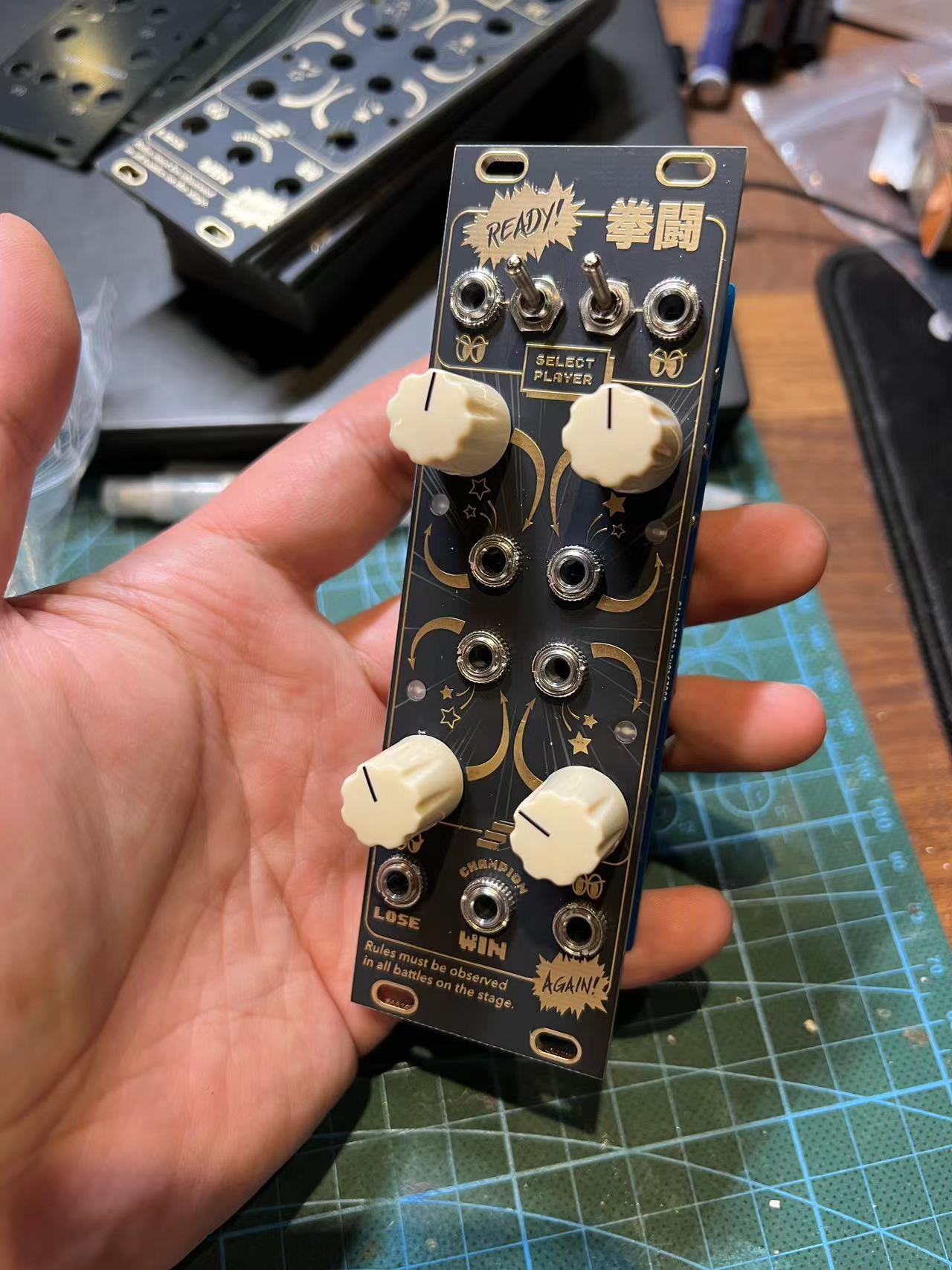
顶部的两个插孔和两个开关构成boxing的控制部分,它是一个二进制的四位输入。便于理解,我们把插孔1和开关2看做选手A,开关3和插孔4看做选手B。对于选手A,当开关2在下位,此时A输入为低电平,记为L,当打到上位,A输入为高电平,记为H,若在插孔1插入信号线,开关2将被旁通,给插孔1一个方波信号,方波峰谷时即输入低电平L,波峰时将输入高电平H。对于选手B,情况和A一样。现在我们将A和B组合起来,即可得到四种情况:LL、LH、HL、HH,这四种情况决定了下面四个输入插孔7、8、9、10哪个和输出插孔14连通。插孔7、8、9、10旁的小星星图案指示了在哪个情况下它会和输出14连通。
简单说,我们可以通过两个方波信号来选择输入插孔7、8、9、10四路信号中的哪一路能在插孔14输出。
当插孔7、8、9、10某一个或多个没有插入信号线时,对应的旋钮5、6、11、12会将一个可调的电压附加到插孔7、8、9、10,通过顶部的控制信号,我们可以将这个电压在插孔14输出,调整旋钮5、6、11、12为不同的电压值,我们可以得到一个四步步进音序输出(有两组方波输入到插孔1和4)或者一组二步步进音序输出(只有一个方波信号给到插孔1或4)。用同样的方式我们可以实现插孔1、4的与门、或门、非门、与非门、或非门逻辑输出,在此不做赘述。
输出插孔13是输出插孔14的差分输出,及插孔13的输出电压为9v减去插孔14的电压(会有一定误差),即插孔14输出高电压,插孔13输出低电压。
插孔15是一个可控的方波输出,它的频率受插孔14的电压影响。
拳斗boxing模块就是一个拳击擂台,通过A和B两位选手的不同出招碰撞,得到最终的三个拳赛结果。
小字备注:一个特别的用法:插孔14可作为输入口来实现反向输入,此时插孔7、8、9、10可输出插孔14的电压,为保留这个特别的用法,无可避免的会带来一定的电压衰减,无论是正向还是反向使用。因此,避免用boxing来导通v/oct的控制电压。
The Boxing module is a multifunctional module based on channel selection. It can implement channel selection, four-step or two-step sequencers, differential signals, square waves, logic functions, and more.
The two jacks and two switches at the top constitute the control part of the Boxing module, which is a binary four-bit input. For ease of understanding, let's consider jack 1 and switch 2 as contestant A, and switch 3 and jack 4 as contestant B. For contestant A, when switch 2 is in the lower position, the A input is at a low level, denoted as L. When switched to the upper position, the A input is at a high level, denoted as H. If a signal cable is inserted into jack 1, switch 2 will be bypassed, providing a square wave signal to jack 1, with the troughs representing a low level L and the peaks representing a high level H. The situation for contestant B is the same as for A. Now, by combining A and B, we get four scenarios: LL, LH, HL, HH. These four scenarios determine which of the four input jacks 7, 8, 9, 10 will be connected to the output jack 14. The small star patterns next to jacks 7, 8, 9, 10 indicate under which scenario they will connect to output 14.
In short, we can use two square wave signals to select which of the four signal paths from input jacks 7, 8, 9, 10 can be output through jack 14.
When one or more of jacks 7, 8, 9, 10 do not have a signal cable inserted, the corresponding knobs 5, 6, 11, 12 will add an adjustable voltage to jacks 7, 8, 9, 10. With the control signals from the top, we can output this voltage through jack 14. By adjusting knobs 5, 6, 11, 12 to different voltage values, we can obtain a four-step sequencer output (with two sets of square waves input to jacks 1 and 4) or a two-step sequencer output (with only one square wave signal given to jack 1 or 4). In the same way, we can implement AND, OR, NOT, NAND, NOR logic outputs with jacks 1, 4, which will not be elaborated here.
Output jack 13 is the differential output of output jack 14, meaning the output voltage of jack 13 is 9v minus the voltage of jack 14 (with some error), i.e., if jack 14 outputs a high voltage, jack 13 outputs a low voltage.
Jack 15 is a controllable square wave output, its frequency is affected by the voltage of jack 14.
The Boxing module is like a boxing ring, where the different moves of contestants A and B collide, resulting in three final match outcomes.
***Note: A special usage is that jack 14 can act as an input port for reverse input, in which case jacks 7, 8, 9, 10 can output the voltage of jack 14. To preserve this special usage, some voltage attenuation is inevitable, whether used in forward or reverse. Therefore, avoid using Boxing to conduct v/oct control voltage.
Boxing